Aerodynamic report · an example
Raven UAV
Flight model from 24 CFD solutions: α 0° to 14°, sideslip, and 12 control deflections. Written by Deneb Aero on 10 October 2026.
- Wing area
- 0.494 m²
- Span
- 2.49 m
- Aspect ratio
- 12.6
- Mean chord
- 0.214 m
- Mass
- 9.5 kg
- CG from the nose
- 0.420 m · 25% MAC
- Cruise speed
- 20 m/s
- Reynolds number
- 2.9 × 10⁵
1Summary
- Best glide
- 13.5L/D at α 4°, CL 0.99
- Stall speed
- 15.2m/s CLmax 1.33 at α 8°, 9.5 kg
- Power at 20 m/s
- 140W airframe drag × speed
- Static margin
- 37% MAC stable in pitch
- Best glide 13.5 at α 4°. At 9.5 kg that is 17.7 m/s for the longest range; minimum power, 113 W, comes at 15.4 m/s for the longest endurance.
- Cruise at 20 m/s: L/D 13.3. Needs CL 0.77 at about α 2.0°. Airframe drag costs 140 W before propeller and motor losses.
- Stall at α 8°, CLmax 1.33. At 9.5 kg the stall speed is 15.2 m/s in sea-level air.
- Stable in pitch · margin 37%. Neutral point 0.50 m behind the nose (62% MAC); with neutral controls it trims at α -1.2° (CL 0.40, extrapolated).
- Weathercock stable. Cnβ 0.055 and Clβ 0.024 per radian from the 5° sideslip run.
2The aircraft and the method
Raven was analysed from Raven.step (5 parts, 100,006 surface triangles; 1.31 × 0.43 × 2.49 m). Coefficients use the wing area, mean chord and span above; moments are taken about the centre of gravity, 0.420 m behind the nose (25% of the mean chord).
Steady, incompressible RANS with the k-ω SST turbulence model and the γ–Reθ transition model (SST-LM), on body-fitted meshes of 5.6–6.3 million cells with 20 prism layers resolving the boundary layer (first-cell y+ 0.5 at the 95th percentile). The aircraft is pitched by α and yawed by β in a box several body lengths across, at 20 m/s in sea-level air (ρ 1.225 kg/m³) with 0.25% freestream turbulence. Loads are averaged over each solution’s final iterations.
Control and sideslip derivatives come from steady, incompressible RANS with the k-ω SST turbulence model, on body-fitted meshes of 2.0–2.1 million cells with wall functions, as increments from the neutral case at α 2° on the same mesh.
3The flow around the Raven
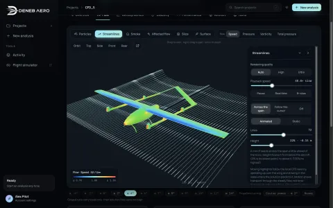
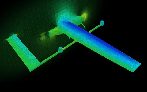
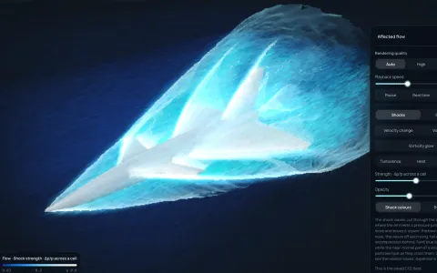
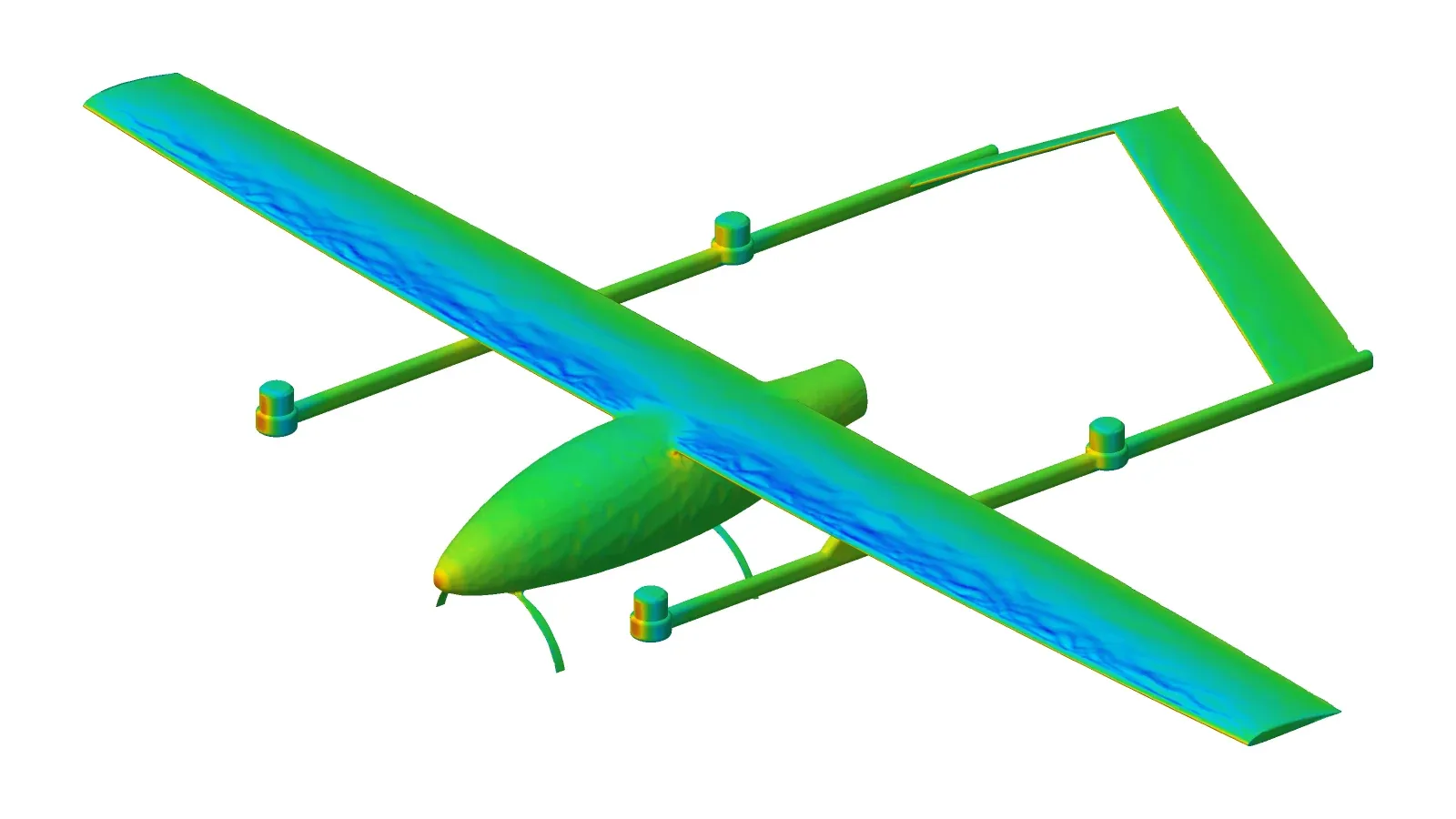
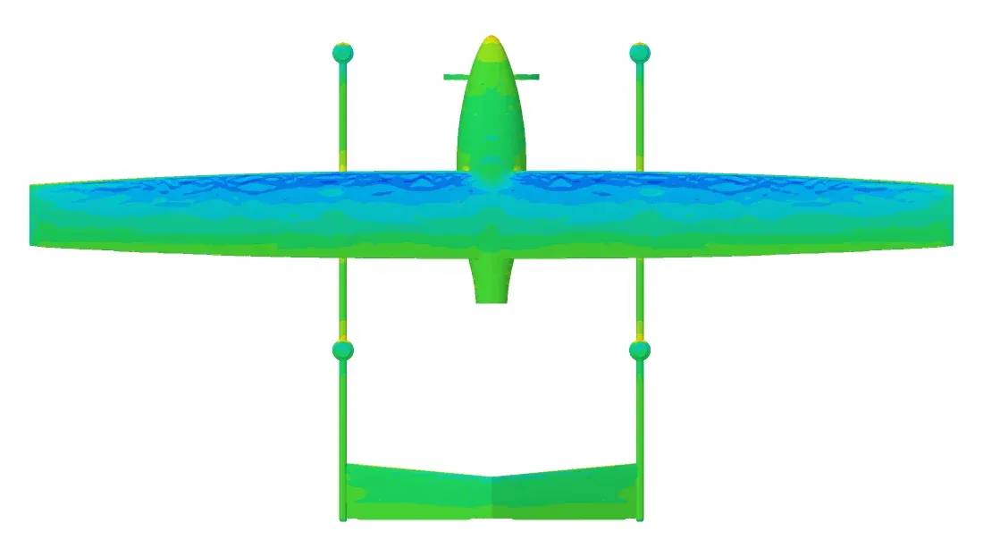
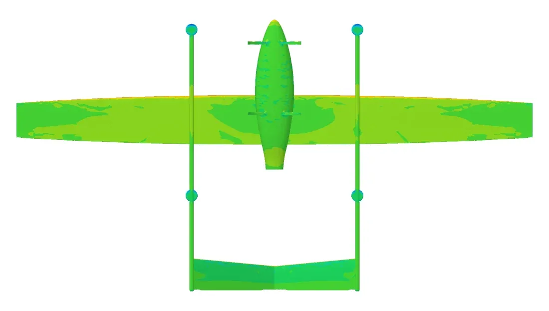
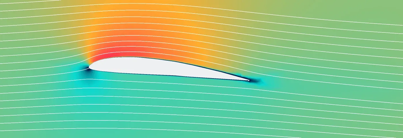
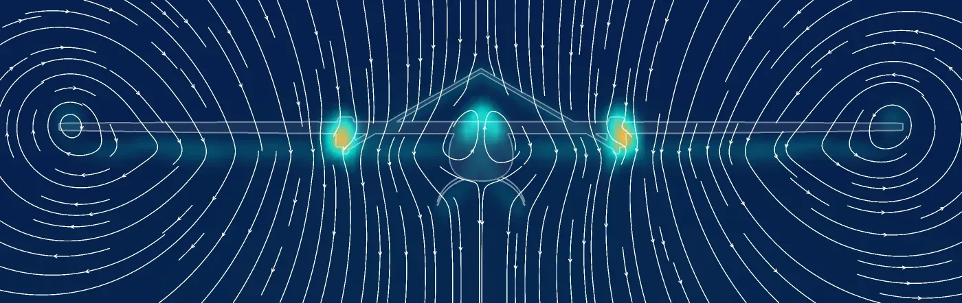
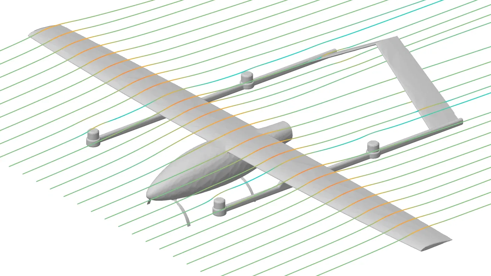
From the solution at α 2° and 20 m/s, as is the pressure picture on the first page: the solver’s wall pressures, cuts through its mesh and streamlines through its flow.
4Aerodynamics
| α | CL | CD | L/D | Cm |
|---|---|---|---|---|
| 0° | 0.533 | 0.0481 | 11.1 | -0.051 |
| 2° | 0.767 | 0.0578 | 13.3 | -0.135 |
| 4° | 0.989 | 0.0731 | 13.5 | -0.218 |
| 6° | 1.199 | 0.0920 | 13.0 | -0.293 |
| 7° | 1.298 | 0.1023 | 12.7 | -0.323 |
| 8° | 1.327 | 0.1205 | 11.0 | -0.355 |
| 9° | 1.290 | 0.1449 | 8.9 | -0.379 |
| 10° | 1.173 | 0.1814 | 6.5 | -0.495 |
| 12° | 1.116 | 0.2361 | 4.7 | -0.539 |
| 14° | 1.081 | 0.2924 | 3.7 | -0.603 |
Neutral controls, β 0°. Lift and drag in wind axes; Cm about the CG on the mean chord, nose-up positive.
5Stability and control
- Static margin
- 37% MAC typically 5–20% for a stable aircraft
- Neutral point
- 0.50m 62% MAC, behind the nose
- Elevator to trim at 20 m/s
- −3.8° at α 2.0°, trailing edge up
- dCm/dCL
- −0.366 the static margin, sign flipped
| Sideslip derivative (β 5° at α 2°) | Per radian | Reading |
|---|---|---|
| Side force CYβ | -0.413 | Restoring |
| Roll Clβ (dihedral effect) | 0.024 | Rolls into the slip |
| Yaw Cnβ (weathercock) | 0.055 | Stable |
| Per degree of deflection | ∂CL/∂δ | ∂Cm/∂δ | ∂CY/∂δ | ∂Cl/∂δ | ∂Cn/∂δ | ΔCD at ±10° |
|---|---|---|---|---|---|---|
| Aileron | −0.0001 | +0.0001 | −0.0002 | +0.0053 | −0.0002 | +0.0070 / +0.0068 |
| Elevator | +0.0101 | −0.0360 | −0.0000 | +0.0000 | −0.0000 | +0.0016 / +0.0067 |
| Rudder | −0.0000 | +0.0001 | +0.0043 | −0.0005 | −0.0014 | +0.0047 / +0.0049 |
From ±5° and ±10° deflections at α 2°, 20 m/s. Body axes: Cl rolls right, Cm pitches nose-up and Cn yaws nose-right when positive.
6Performance
- Stall speed
- 15.2m/s CLmax 1.33 at α 8°, 9.5 kg
- Best range speed
- 17.7m/s L/D 13.5
- Best endurance
- 15.4m/s 113 W airframe power
- At 20 m/s
- 140W L/D 13.3 at α 2.0°
Speeds are true airspeed at sea level. Electrical power is higher: divide by the propeller’s efficiency (typically 0.6–0.75) and the motor’s and ESC’s (0.8–0.9).
AComputations
| Case | Model | Cells | Iterations | Wall time | Loads |
|---|---|---|---|---|---|
| α 0° | SST-LM, wall-resolved | 5.60 M | 607 | 1 h 20 min | Steady loads |
| α 2° | SST-LM, wall-resolved | 5.65 M | 575 | 1 h 18 min | Steady loads |
| α 4° | SST-LM, wall-resolved | 5.76 M | 730 | 1 h 36 min | Steady loads |
| α 6° | SST-LM, wall-resolved | 5.79 M | 803 | 1 h 42 min | Steady loads |
| α 7° | SST-LM, wall-resolved | 5.90 M | 939 | 1 h 58 min | Steady loads |
| α 8° | SST-LM, wall-resolved | 5.90 M | 1063 | 2 h 14 min | Steady loads |
| α 9° | SST-LM, wall-resolved | 5.94 M | 1157 | 2 h 28 min | Steady loads |
| α 10° | SST-LM, wall-resolved | 6.05 M | 1004 | 2 h 15 min | Steady loads |
| α 12° | SST-LM, wall-resolved | 6.14 M | 864 | 1 h 58 min | Steady loads |
| α 14° | SST-LM, wall-resolved | 6.29 M | 681 | 1 h 37 min | Steady loads |
| α 2° · control baseline | SST, wall functions | 2.04 M | 404 | 52 min | Converged |
| α 2° · β 5° | SST, wall functions | 2.05 M | 404 | 42 min | Converged |
| α 2° · aileron −10° | SST, wall functions | 2.04 M | 404 | 42 min | Converged |
| α 2° · aileron −5° | SST, wall functions | 2.04 M | 404 | 46 min | Converged |
| α 2° · aileron +5° | SST, wall functions | 2.04 M | 404 | 54 min | Converged |
| α 2° · aileron +10° | SST, wall functions | 2.04 M | 404 | 54 min | Converged |
| α 2° · elevator −10° | SST, wall functions | 2.04 M | 404 | 53 min | Converged |
| α 2° · elevator −5° | SST, wall functions | 2.04 M | 404 | 53 min | Converged |
| α 2° · elevator +5° | SST, wall functions | 2.04 M | 404 | 53 min | Converged |
| α 2° · elevator +10° | SST, wall functions | 2.04 M | 404 | 54 min | Converged |
| α 2° · rudder −10° | SST, wall functions | 2.04 M | 404 | 54 min | Converged |
| α 2° · rudder −5° | SST, wall functions | 2.04 M | 404 | 53 min | Converged |
| α 2° · rudder +5° | SST, wall functions | 2.04 M | 404 | 53 min | Converged |
| α 2° · rudder +10° | SST, wall functions | 2.04 M | 404 | 53 min | Converged |
Generated by Deneb Aero from the solutions above.