The Raven in the hover
Four lift rotors at 23.3 N each, the air drawn in above them and thrown down below. Their jets push down on the wing with 2.1 N, 2.2% of their thrust.
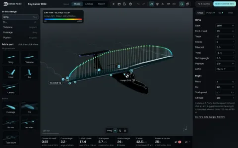 DesignSTEP or a drawing to aerodynamics in seconds: vortex lattice, 3D panels.
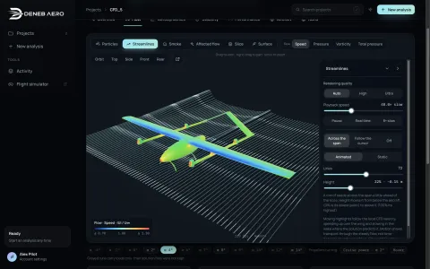 CFD StudioSTEP to a RANS polar: SST and SST-LM, on your computer.
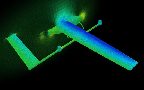 DenebMeshDeneb’s own mesher for aircraft.
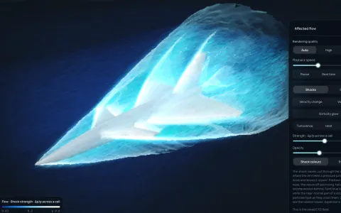 SupersonicShocks, schlieren and the sonic boom, from Mach 0.3 up.
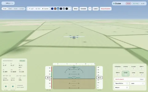 Flight simulationFly the result: Gazebo with ArduPilot SITL.
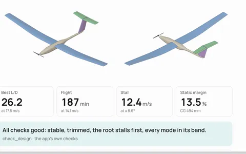 MCPYour AI agent designs with Deneb Design’s own analysis.
CFD Studio
Open your UAV’s or drone’s CAD. The Studio plans the runs, meshes it and solves each attitude as a steady RANS solution, on your own computer. You get the polar, stability and performance, the flow in 3D and a report.
An analysis is set up in one sitting. The runs are queued and solved one after another, and the Studio can be closed while they run.
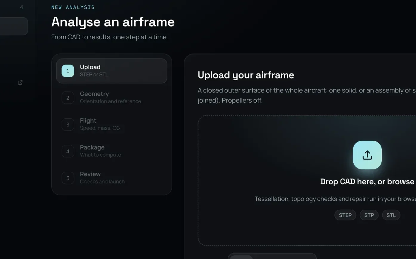
A STEP or STL file of the whole aircraft. It is read, joined into one closed surface and checked on your computer.
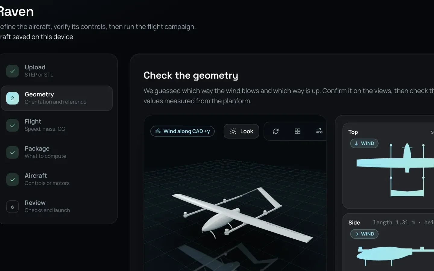
Which way the wind blows and which way is up, guessed from the shape; the span, chord and area measured.
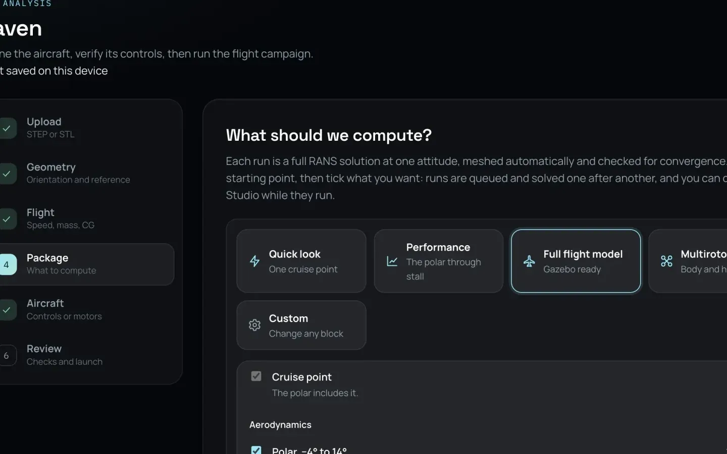
A Quick look, a polar to stall, or the full flight model with controls and sideslip, with the hours each takes.
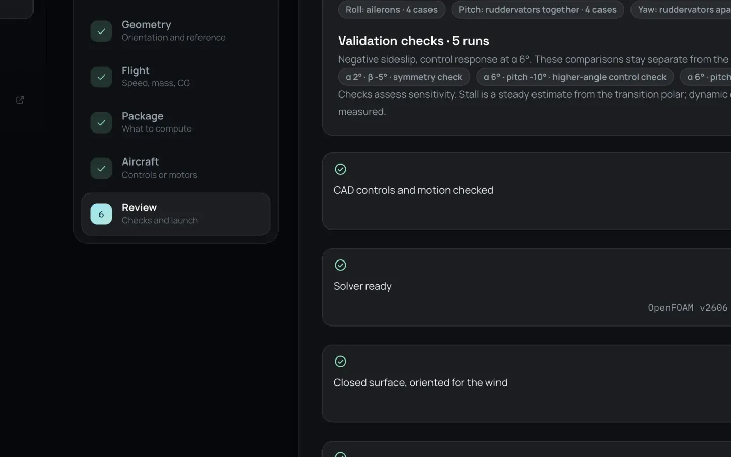
The controls, the solver, the closed surface and the largest mesh against your memory, checked before anything is queued.
An example: the Raven
Each point is one wall-resolved CFD run at 20 m/s, from 0° to 14°. Best glide 13.5 at 4°, the stall at 8° with a maximum lift coefficient of 1.33.
From the sample report: ten runs of 5.6 to 6.3 million cells, 1 h 18 min to 2 h 28 min each.
Turbulence models
A Quick look solves with k-ω SST and wall functions: a coarser mesh and a quicker first answer. A polar resolves the boundary layer down to the wall and lets it stay laminar until it turns: k-ω SST-LM, the transition model. Here is the Raven at 2° and 20 m/s, both ways.
| Quick look | Polar | |
|---|---|---|
| Turbulence model | k-ω SST | k-ω SST-LM (transition) |
| At the wall | Wall functions | Wall-resolved, y⁺ under 2 |
| Cells | 2.04 M | 5.65 M |
| Wall time | 52 min | 1 h 18 min |
| Lift coefficient | 0.706 | 0.7678.6% more lift |
| Drag coefficient | 0.0573 | 0.0578 |
| Lift to drag | 12.3 | 13.3 |
The transition run knows where the boundary layer is laminar and where it is turbulent, and the flow viewer draws it on the skin. Open the Raven and choose Surface, then Laminar / turbulent.
Against a wind tunnel
A sub-scale model whose shape and tunnel results NASA published. Solved with the Studio’s standard settings, fully turbulent k-ω SST at 2° and 4°: the drag within 1.6% of the tunnel’s at both angles and the pitching moment’s slope within 9%, the lift 6 to 7% high at the same angle.
On DenebMesh’s mesh. The model’s as-built wing and tail setting were not published, which may account for the lift’s offset. Tunnel: NASA LaRC 12-Foot Low-Speed Tunnel, propellers off (Simmons, Geuther and Ahuja, AIAA AVIATION 2023, Fig. 8). The same case on both meshers, in 3D
Rotors and propellers
Each rotor is solved as an actuator disk at its measured thrust. The Studio works out what each rotor’s air does to the airframe, and the flight model flies it, scaled with each motor’s live thrust.
Four lift rotors at 23.3 N each, the air drawn in above them and thrown down below. Their jets push down on the wing with 2.1 N, 2.2% of their thrust.
The pusher at 6.0 N. Its slipstream through the V-tail changes the pitching-moment coefficient by +0.0123 and the drag coefficient by +0.0020.
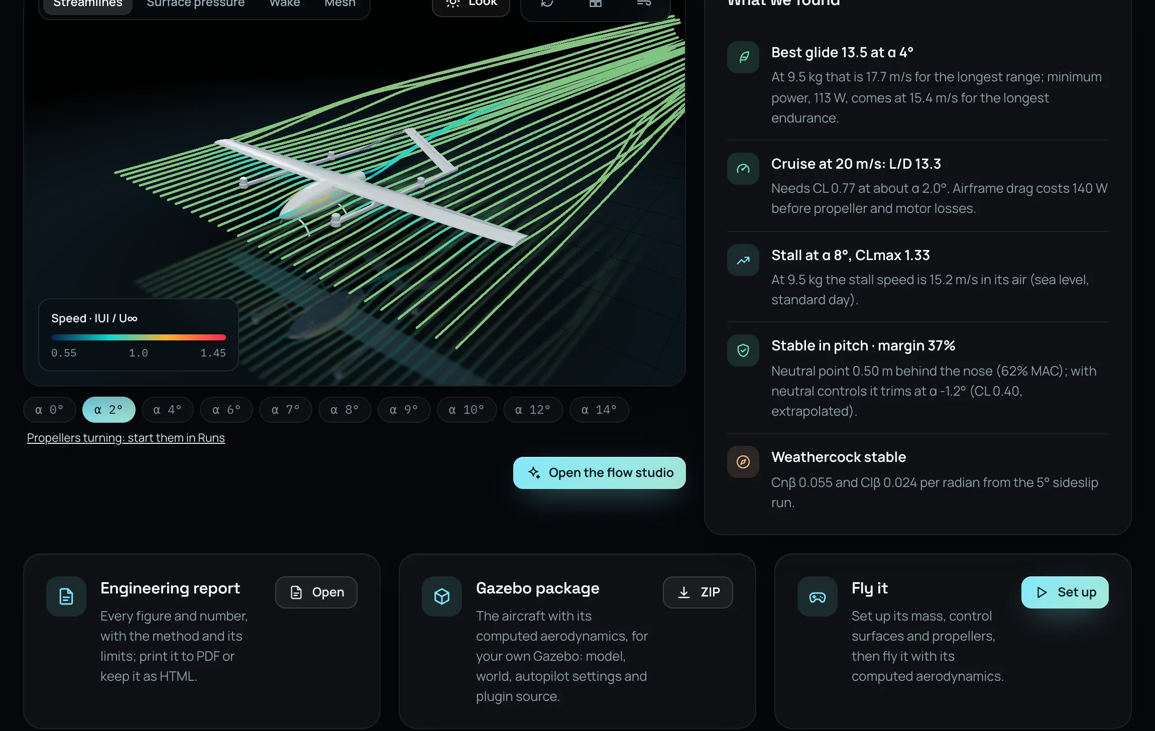
A finished project opens on what was found: best glide, cruise, stall, balance. Behind it, a tab for each question, with the method and its limits beside each number.
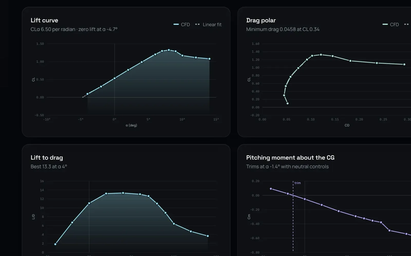
The lift curve, drag polar, lift to drag and pitching moment, and every coefficient in a table.
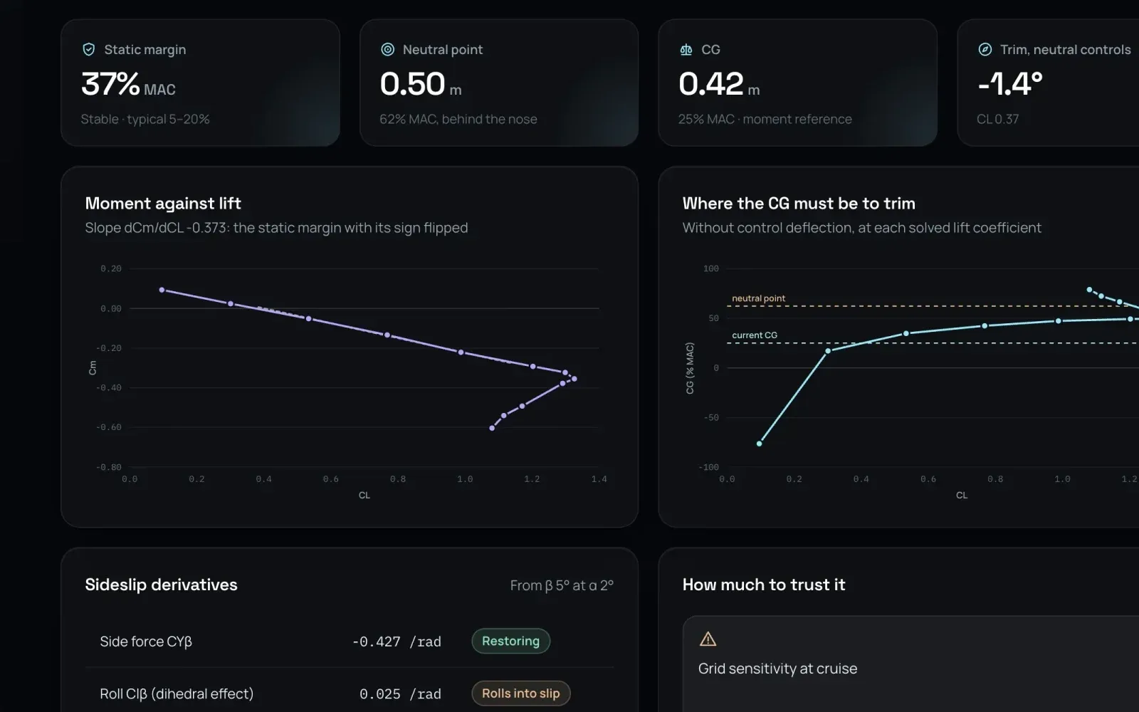
Static margin and neutral point, where the CG must be to trim, the sideslip derivatives and how much to trust each.
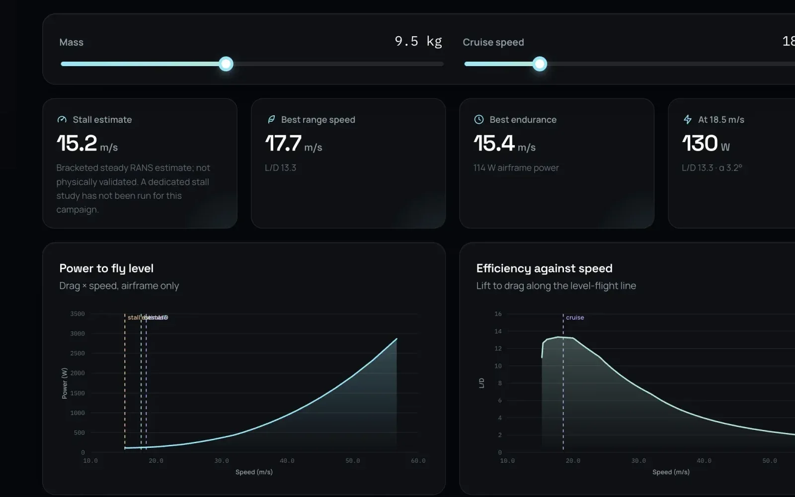
Stall speed, best range and endurance, the power to fly level, flight time on your battery and the ceilings.
Studies
A study is a named group of analyses: one aircraft and its variants. Mark one Baseline and every other shows its difference from it, grey where the difference is within the noise of the solution.
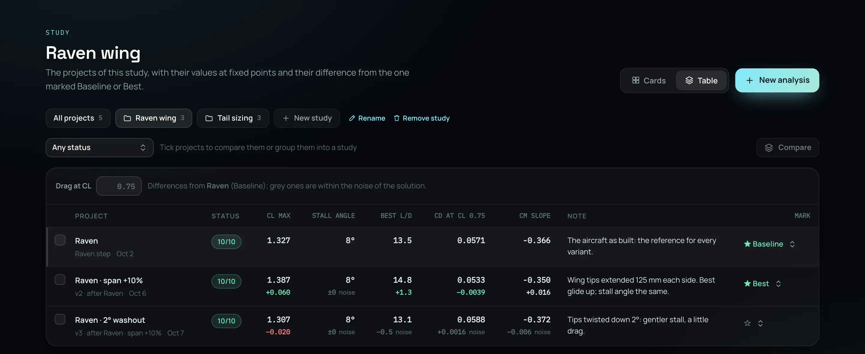
Put projects in a study from the table, as many studies as you like; a project can be in several.
Each difference is judged against the uncertainty of both results, so a change smaller than the noise reads as noise.
Tick two to four projects for Compare: what changed in the design, the polars overlaid and the flow side by side.
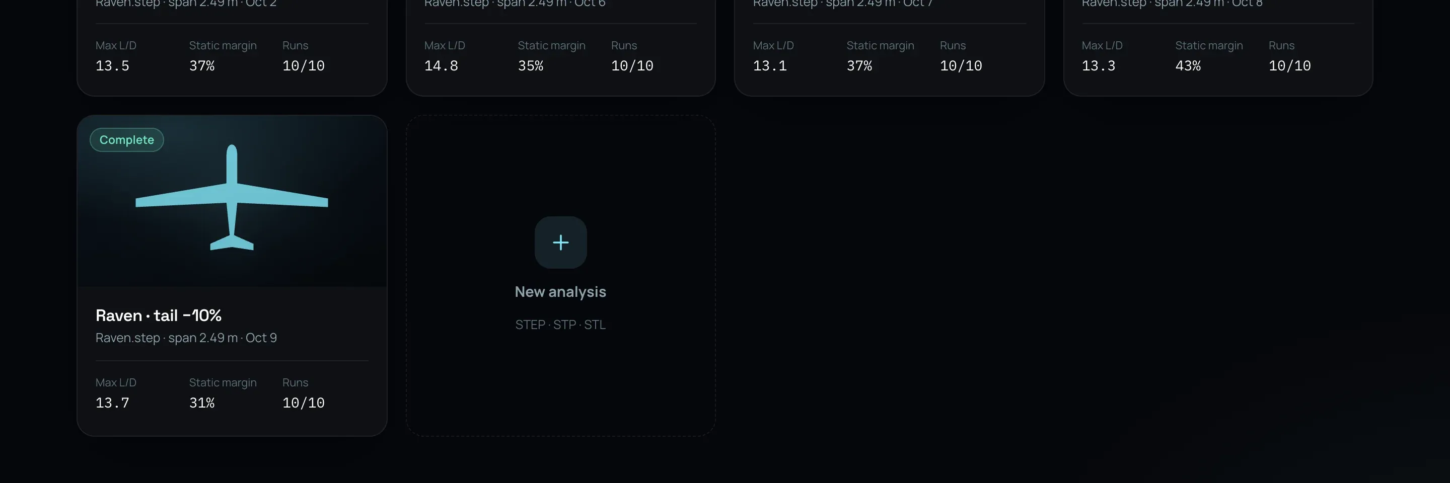
An illustrative workspace: the Raven is the real run; its variants and their numbers are made up for this picture.
The report
Summary, the aircraft and the method, the flow, aerodynamics, stability and control, performance, and every computation. As HTML, or printed to PDF.
Read the Raven’s report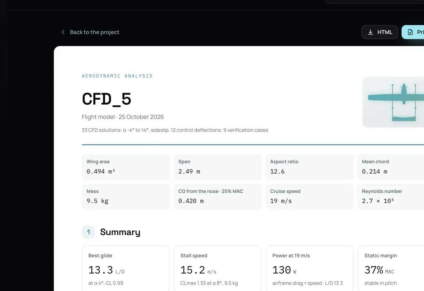
The solved aerodynamics become a Gazebo package with ArduPilot, flown on your computer. Flight simulation · How it is meshed
We use cookies to see how our sites are used and make them better. Your choice applies to all Deneb Systems sites. Learn more