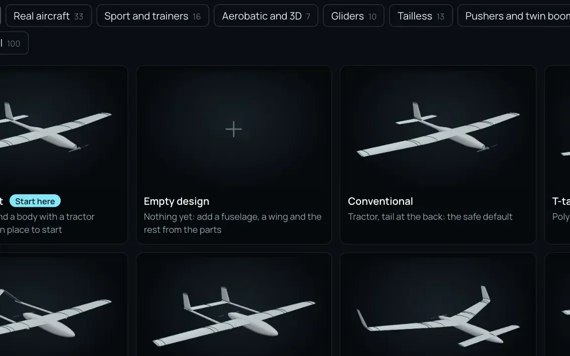
100 templates in 11 groups
Trainers, gliders, tailless, pushers and twin booms, canards, VTOL, twins, jets, and replicas of real aircraft.
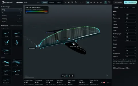 DesignSTEP or a drawing to aerodynamics in seconds: vortex lattice, 3D panels.
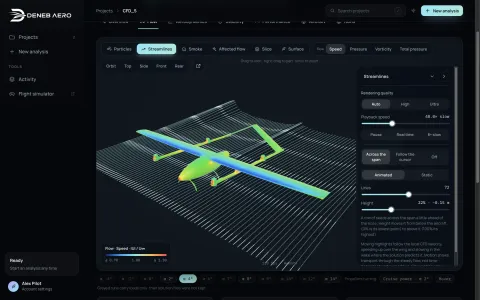 CFD StudioSTEP to a RANS polar: SST and SST-LM, on your computer.
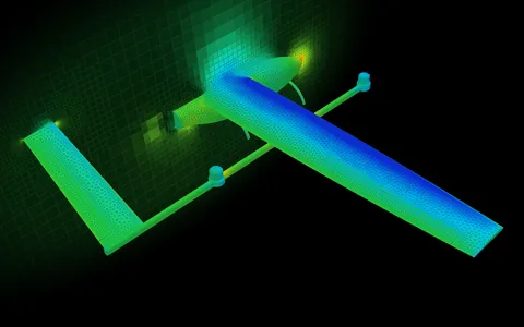 DenebMeshDeneb’s own mesher for aircraft.
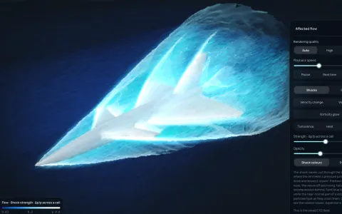 SupersonicShocks, schlieren and the sonic boom, from Mach 0.3 up.
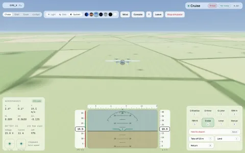 Flight simulationFly the result: Gazebo with ArduPilot SITL.
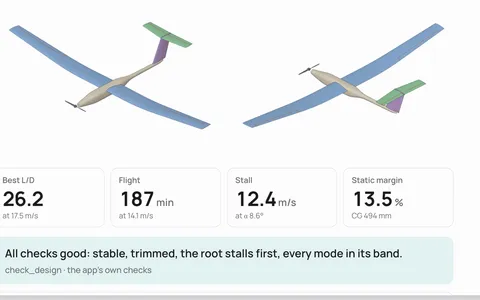 MCPYour AI agent designs with Deneb Design’s own analysis.
Design
Parametric design for UAVs and drones, fixed-wing and VTOL. Add wings, tails, bodies and motors, then drag their handles: lift, stall speed, static margin and power are worked out again on your computer after each change.
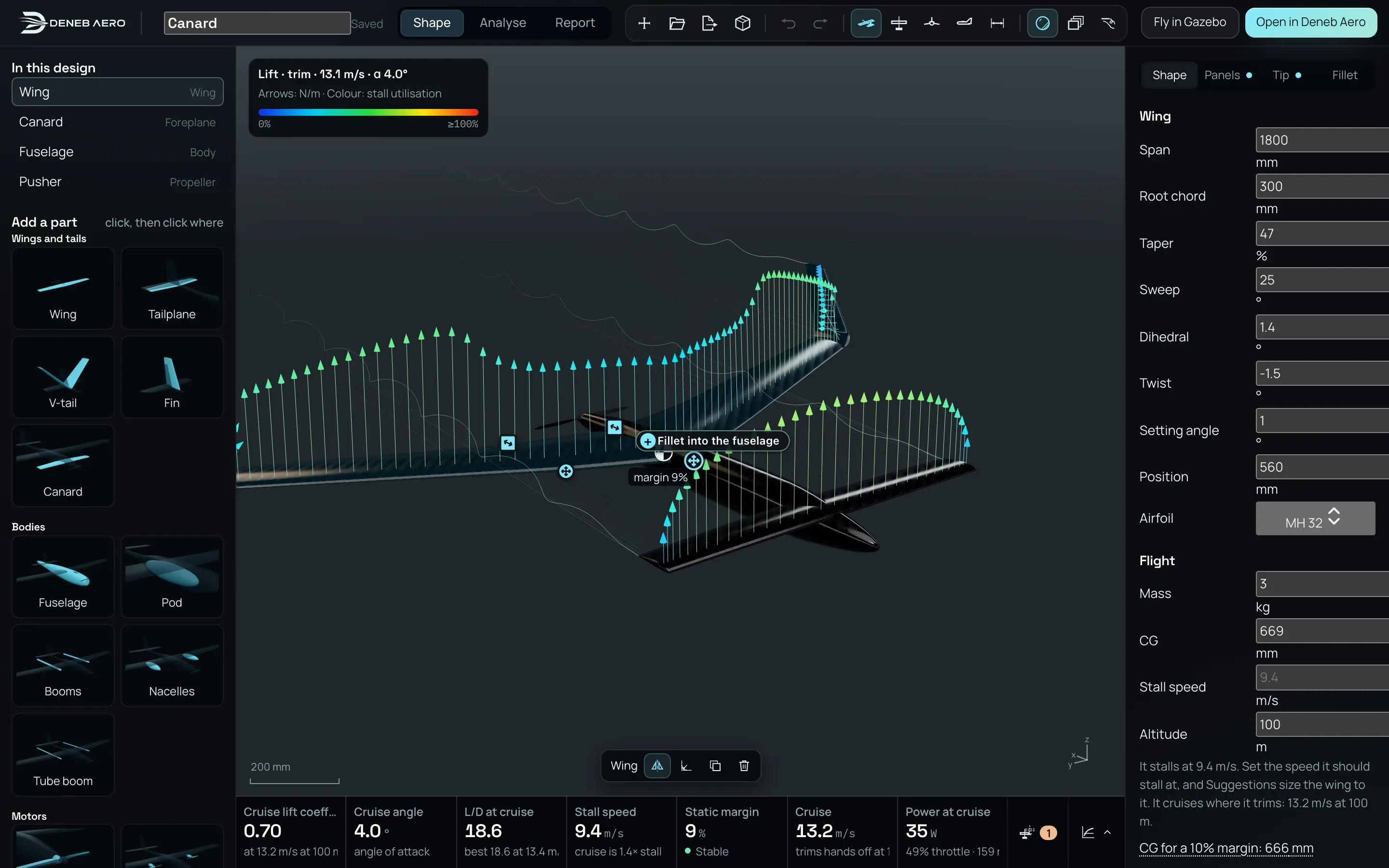
A design is a list of parts with numbers. Wherever it starts, every part stays editable: its span, its sweep, its airfoil, its place.
Trainers, gliders, tailless, pushers and twin booms, canards, VTOL, twins, jets, and replicas of real aircraft.
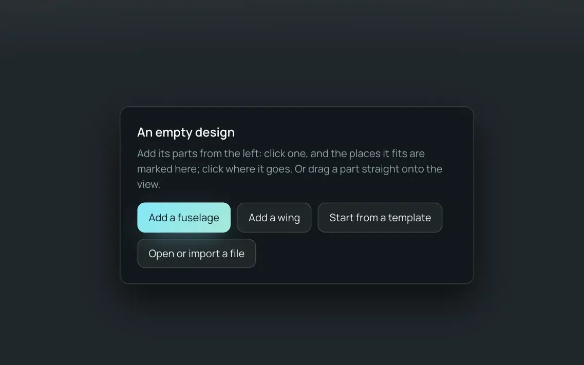
Add a fuselage or a wing, then click a part and click where it goes on the aircraft.
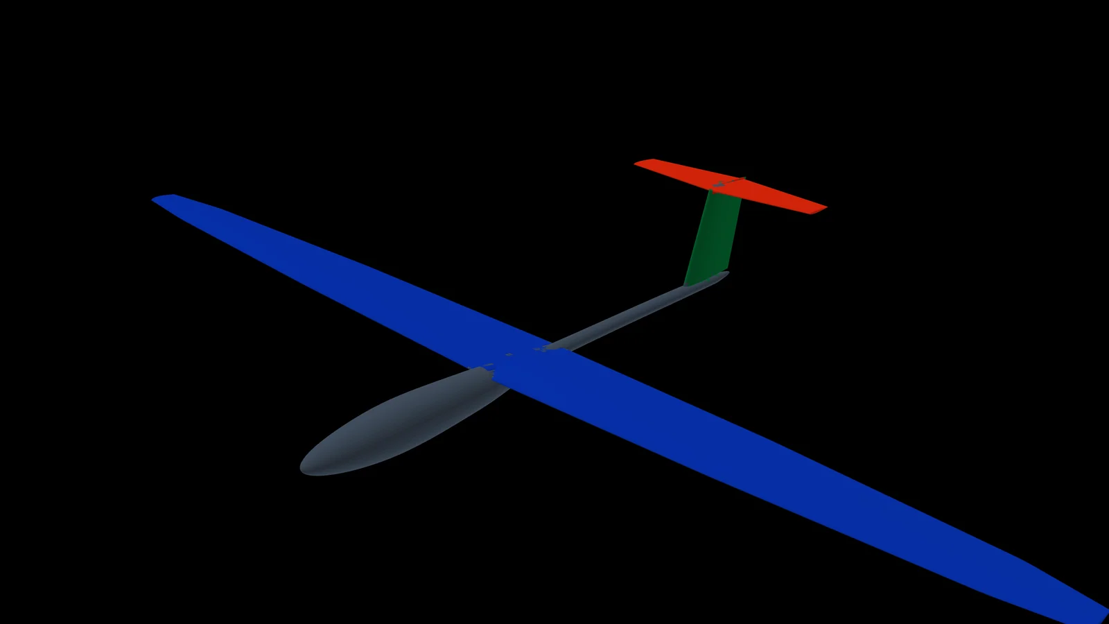
A neural network labels the file’s surface part by part (wing, tailplane, fin, fuselage, boom, pod, propeller), and Design rebuilds each as a part you can edit. The file is read in your browser. See how it reads a file.
From CAD to a vortex lattice
Drop a STEP or STL file into Design. A neural network trained on aircraft looks at every patch of its surface and says what it is: wing, tailplane, fin, fuselage, boom, propeller. Design then fits each one as a part you can edit, ready for the vortex lattice and the panel method in seconds.
A vortex lattice needs each lifting surface as a planform: its span, its chords, its sweep, dihedral and twist, and an airfoil at each section. A STEP file has none of that. It is a pile of surfaces, and nothing in it says which one is a wing, where the wing ends and the fuselage begins, or that a slot is an aileron’s hinge and not a gap in the wing.
It labels the surface part by part. With the labels, Design cuts each part into sections, finds its airfoils, panels and tips, and leaves screws, landing gear and fittings out. What comes back is a design to edit, not a frozen mesh.
Elsewhere, getting a CAD model into a vortex-lattice or panel code means drawing it again, part by part, from its measurements. Design does it for you.
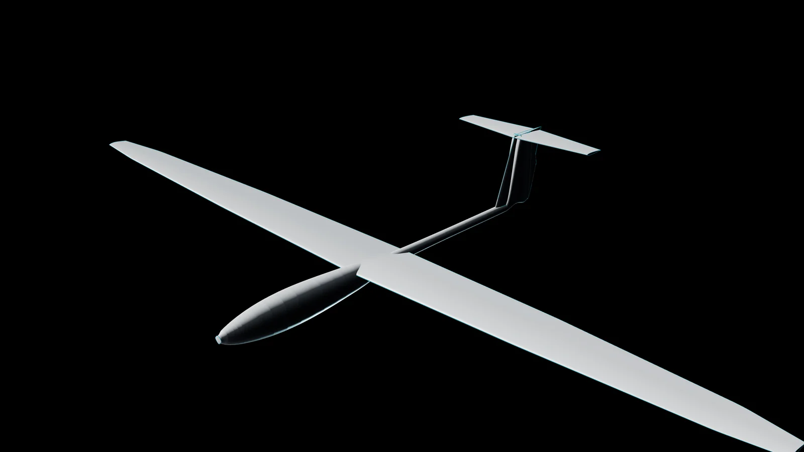
Live wake Preview
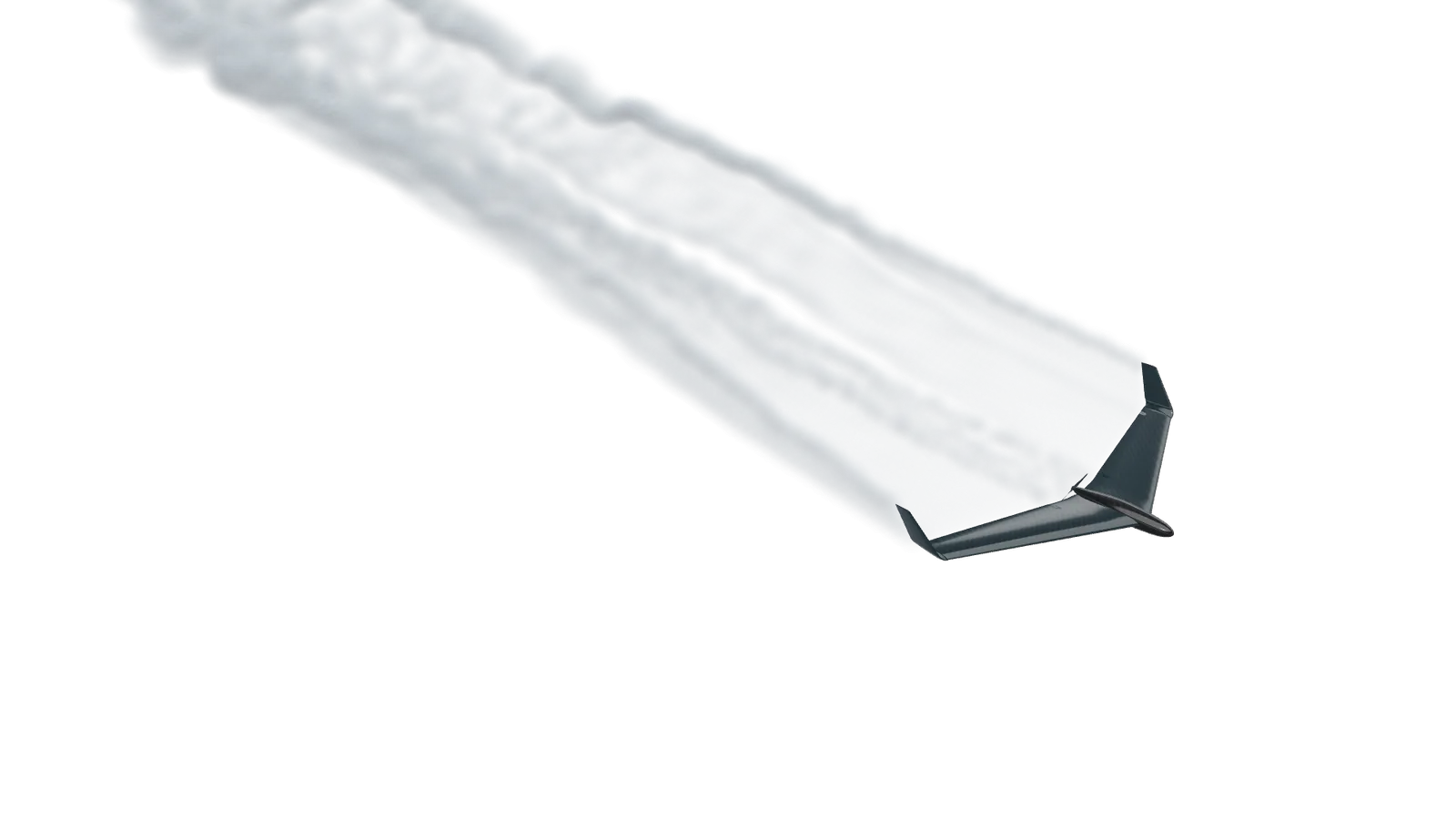
The lattice marched in time on your graphics card: the wake rolls up into the tip vortices and the propeller’s slipstream. It is an inviscid model: lift and induced drag, not the stall.
Live analysis
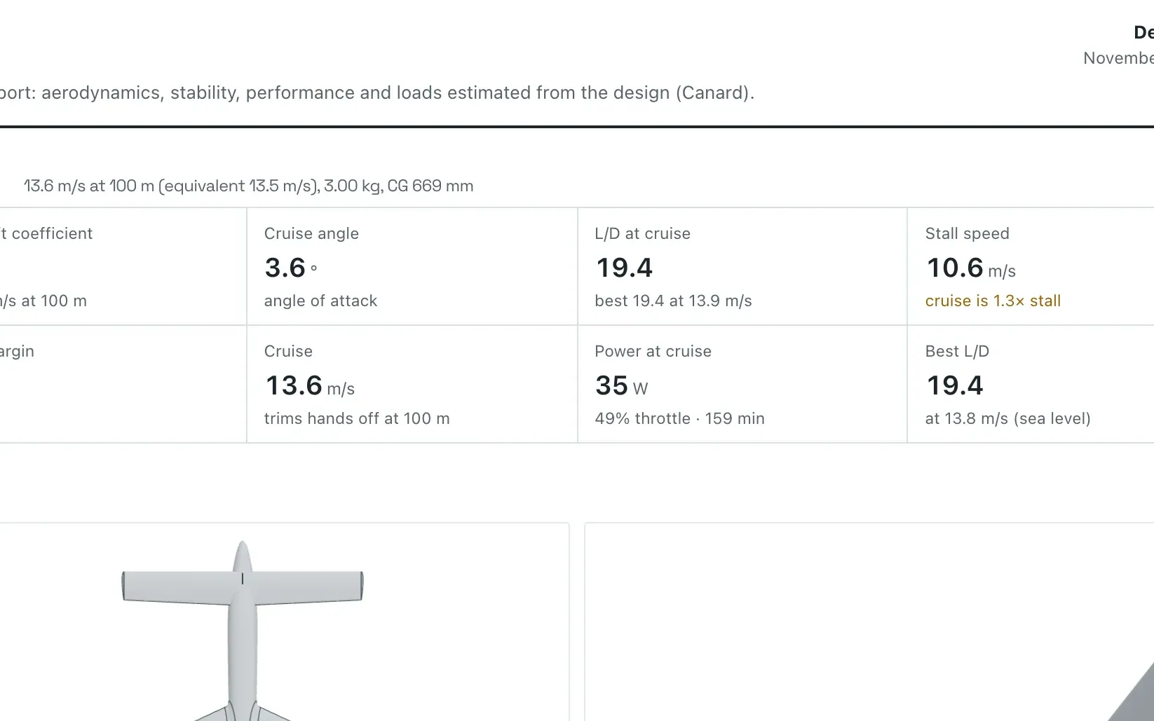
Cruise lift coefficient, cruise angle, L/D, stall speed, static margin, cruise speed and power sit under the view, with their charts one click away. They are estimates from a vortex lattice, not CFD.
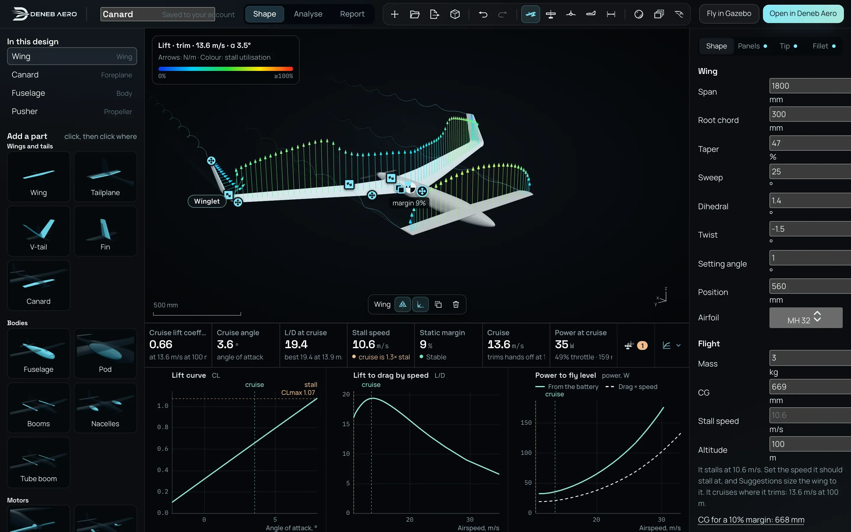
Each strip’s lift per metre of span, amber then red as a section nears its stall.
The centre of gravity, the neutral point and the static margin between them.
A diverging spiral mode or a stall speed that is too high comes with a change, drawn over the aircraft before you apply it.
Suggestions
Suggestions checks the design as you draw it. Each problem comes with a change, drawn as a ghost over the aircraft, and a search tries sizes for the layout you have and keeps the longest flight.
Left alone in a bank, this aircraft tightens into a spiral dive. The fix is 2.1° more dihedral on the outer panel: shown as a ghost, then applied, and nothing is left to fix.
Find it searches the wing’s span, chord and taper, the tail and the fin for the longest flight, every design it tries balanced and trimmed. Here the flight goes from 156 to 193 minutes and the stall from 13.1 to 12.7 m/s. The search is shown faster than it ran.
Fillets, joints, winglets
Where a wing meets the body, Design lays a fillet and checks it. Panels blend into each other over a radius, and a tip takes a winglet. Each is a few numbers you can change, and the flight numbers follow.
The cursor picks Winglet for the tip. The winglets appear on the drawing, and the numbers under it change at once: best lift to drag from 23.1 to 24.1, the stall speed down from 13.1 to 12.8 m/s.
On the Fillet tab the cursor picks Round. A fillet is laid where the wing meets the fuselage and checked, and the analysis runs again with it.
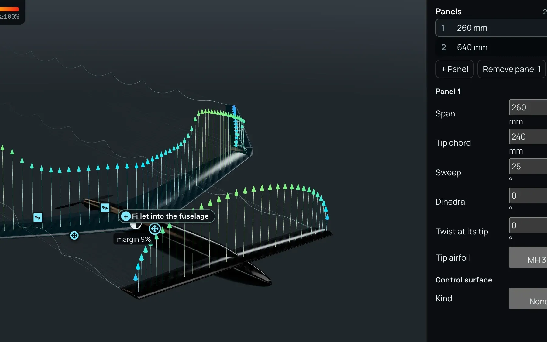
A wing is a row of panels. Each joint blends over a radius you set, so a cranked wing has no sharp break.
Each edit runs the vortex lattice and the section polars again, in the browser: lift, drag, stall speed, balance and power follow the drawing as you change it.
Analyse and report
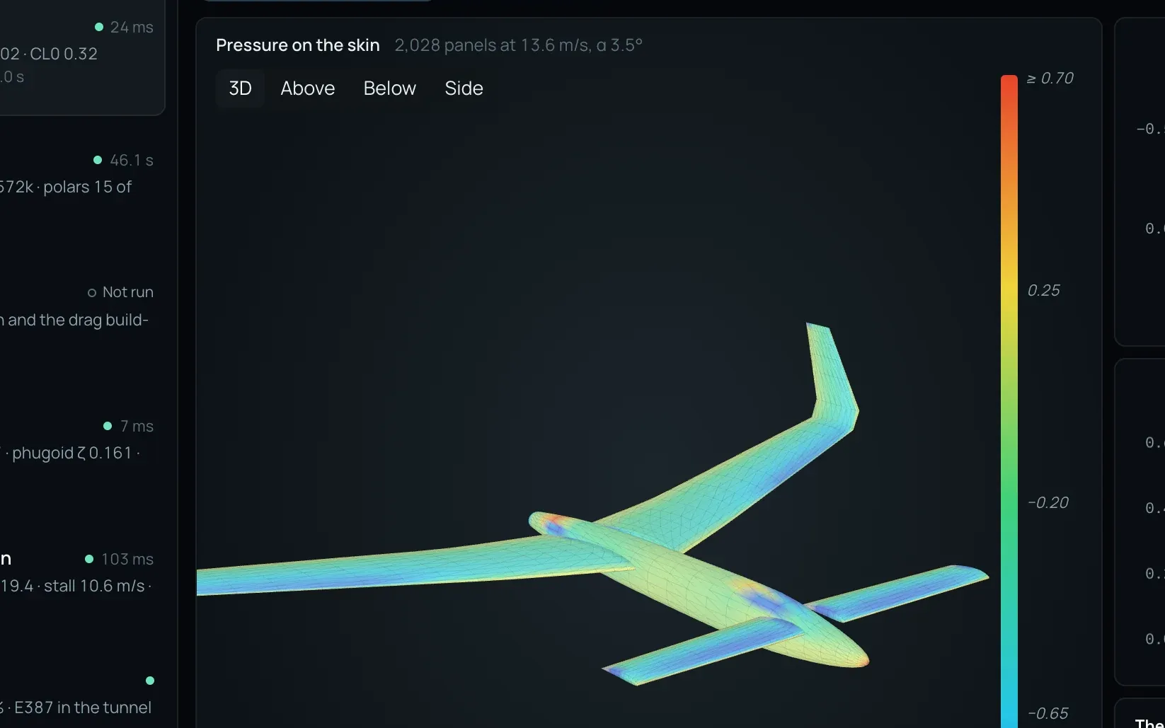
The vortex lattice in plan and the mesh of the panel method, with their counts.
Lift from the lattice at once; pressure everywhere from the panel method.
Each airfoil’s polars at the Reynolds numbers flown, and its boundary layer.
Transition along the span and the drag by speed: induced, profile, bodies.
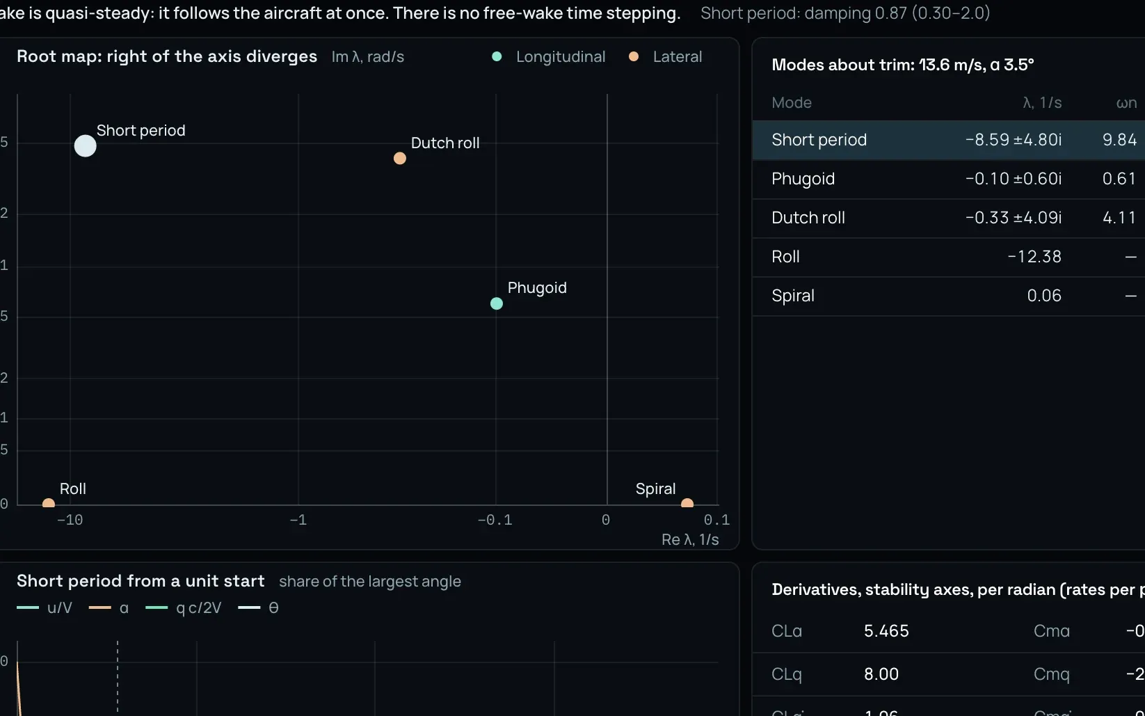
Short period, phugoid, Dutch roll, roll and spiral, each with its damping.
The polar, trim and stall, the controls, performance on the battery, wing loads.
How far each method is from a known answer, and the package for CFD.
The aero database in the flight model’s format, as a CSV file.
Motors
SunnySky motors in 70 frame sizes, each with its datasheet and the propellers the maker tests it with. Pick one in the library and click the propeller to fit it. Thrust, current, flight time and climb become those of the parts you will buy.
Photoreal
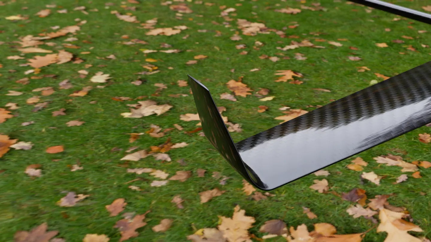
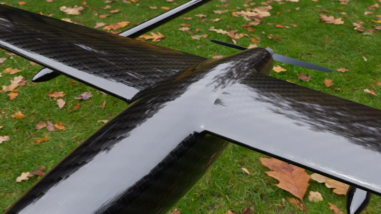
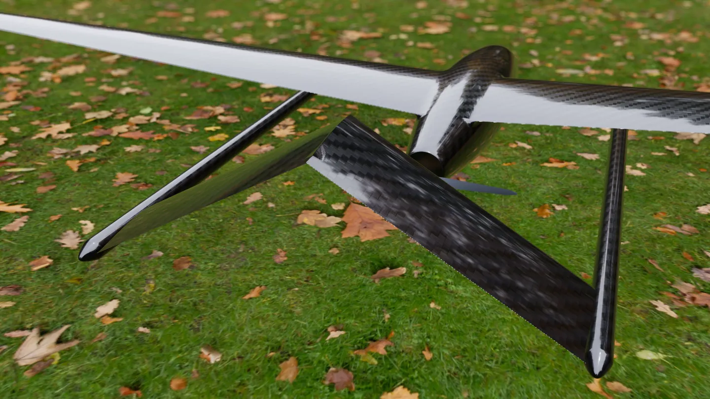
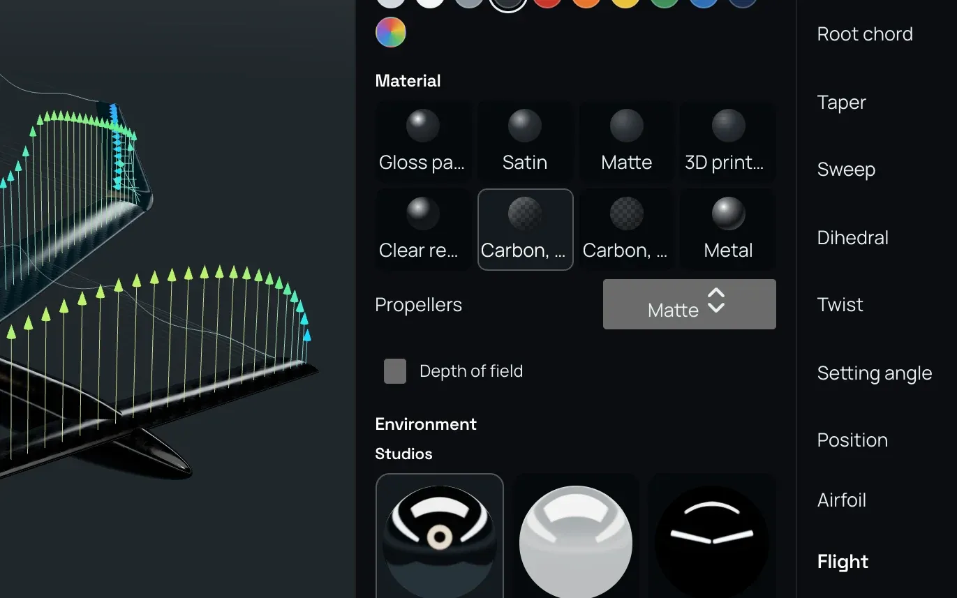
Gloss paint, satin, carbon, printed plastic or metal, in a studio or on a photographed place: snow, a forest, a city, or your own panorama. This film is Design’s own view, with depth of field.
Hand it on
When the shape is right, the aircraft leaves Design as solids, with each control surface cut free of its wing so that it can move.
A new analysis with the parts as solids: the CFD of the aircraft you drew.
A flight in the simulator on your computer, on Design’s estimate of the aerodynamics.
A ZIP for your own Gazebo and ArduPilot.
A STEP file with each part a named solid, for your CAD system.
Design draws aircraft only; it is not a general CAD program. Its numbers are estimates from its own methods. For the stall, the drag of the whole airframe and the flow itself, hand the aircraft on to an analysis.
We use cookies to see how our sites are used and make them better. Your choice applies to all Deneb Systems sites. Learn more