Shape
The Shape mode is where you build and edit the aircraft. The aircraft is in the middle, its parts are on the left, the numbers of the picked part are on the right, and the results are under the view.
The parts
The list In this design shows each part with its kind: Wing, Tailplane, Fin, Body, Propeller and so on. To pick a part, select it in the list or in the view. The part is highlighted, its handles appear in the view, and its numbers appear on the right. Press Esc to let go of the part.
When a part is picked, a bar appears at the bottom of the view with its name and these buttons:
- Both sides (or A pair)
Mirrors the part to the other side of the aircraft.
- Fillet
Adds a fillet at a joint of the part, or removes it. Shown when the part can have one. See Fillet.
- Duplicate
Adds a copy of the part beside it (⌘D, Ctrl+D).
- Delete
Removes the part (Delete or Backspace).
Add a part
The Add a part list shows the parts that can be added, in four groups: Wings and tails, Bodies, Motors and Controls. Each tile shows the part on an aircraft. Below them, SunnySky motors adds a real motor (Motors and Propellers).
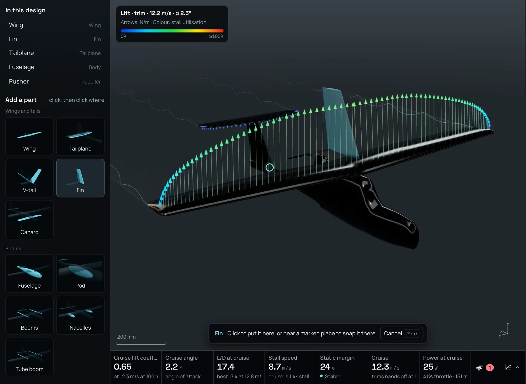
Placing a fin. The strip at the bottom says what a click does.
To add a part by clicking:
Select the tile of the part, for example Fin. The view marks the places where the part fits.
Point at a place. The part is shown as a ghost there. The strip at the bottom of the view says what a click does, for example Click to put it here, or near a marked place to snap it there.
Click. The part is added and picked.
To cancel, select Cancel or press Esc.
To add a part by dragging, drag the tile onto the view and release it where the part goes.
A control (aileron, flap, elevon, elevator, rudder or ruddervator) is added on a wing or a tail where it fits.
Edit the numbers of a wing
Pick a wing, a tail or a fin. The panel on the right has four tabs: Shape, Panels, Tip and Fillet. A dot on a tab means the part has a control surface, a shaped tip, or a fillet.
You change a number in three ways: type a value and press Enter; press ↑ or ↓ to step it (Shift for ten steps, Alt for a tenth); or drag its label sideways. The results under the view follow while you drag, and the whole drag is one undo step. Esc puts back the value you were typing.
The Shape tab
The overall numbers of the part:
Span |
Tip to tip for a pair, root to tip for a single part. For a fin it is Height. |
Root chord |
The chord at the root. The chords out to the tip keep their share of it. |
Taper |
The tip chord as a share of the root chord. |
Sweep |
The angle of the leading edge back from square. |
Dihedral |
How far the tip rises, as an angle. |
Twist |
The angle of the tip to the root, nose up. A negative value is washout. Wings only. |
Setting angle |
The angle of the part to the body. |
Position |
Where the leading edge of the root is, measured from the nose. |
Airfoil |
The airfoil of the part. Select it to choose another one. |
In the view you can drag the handles of the part: its position, its tips and its chords.
Panels
A wing is made of panels, numbered from the root to the tip. Each panel has its own numbers.
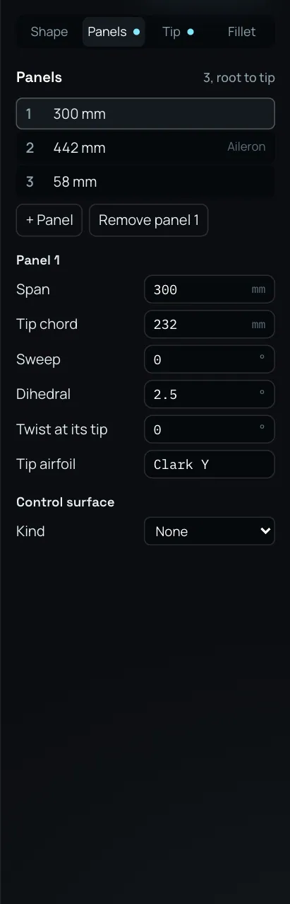
The Panels tab.
Select the Panels tab. Select a panel in the list to edit it. When you point at a panel in the list, it is shown in the view.
Change Span, Tip chord, Sweep, Dihedral and Twist at its tip. For a panel other than the first there is also Joint blend, the radius that rounds the joint at its root. Tip airfoil is the airfoil at the tip of the panel.
To add a panel past the tip, select + Panel. To take a panel away, select Remove panel.
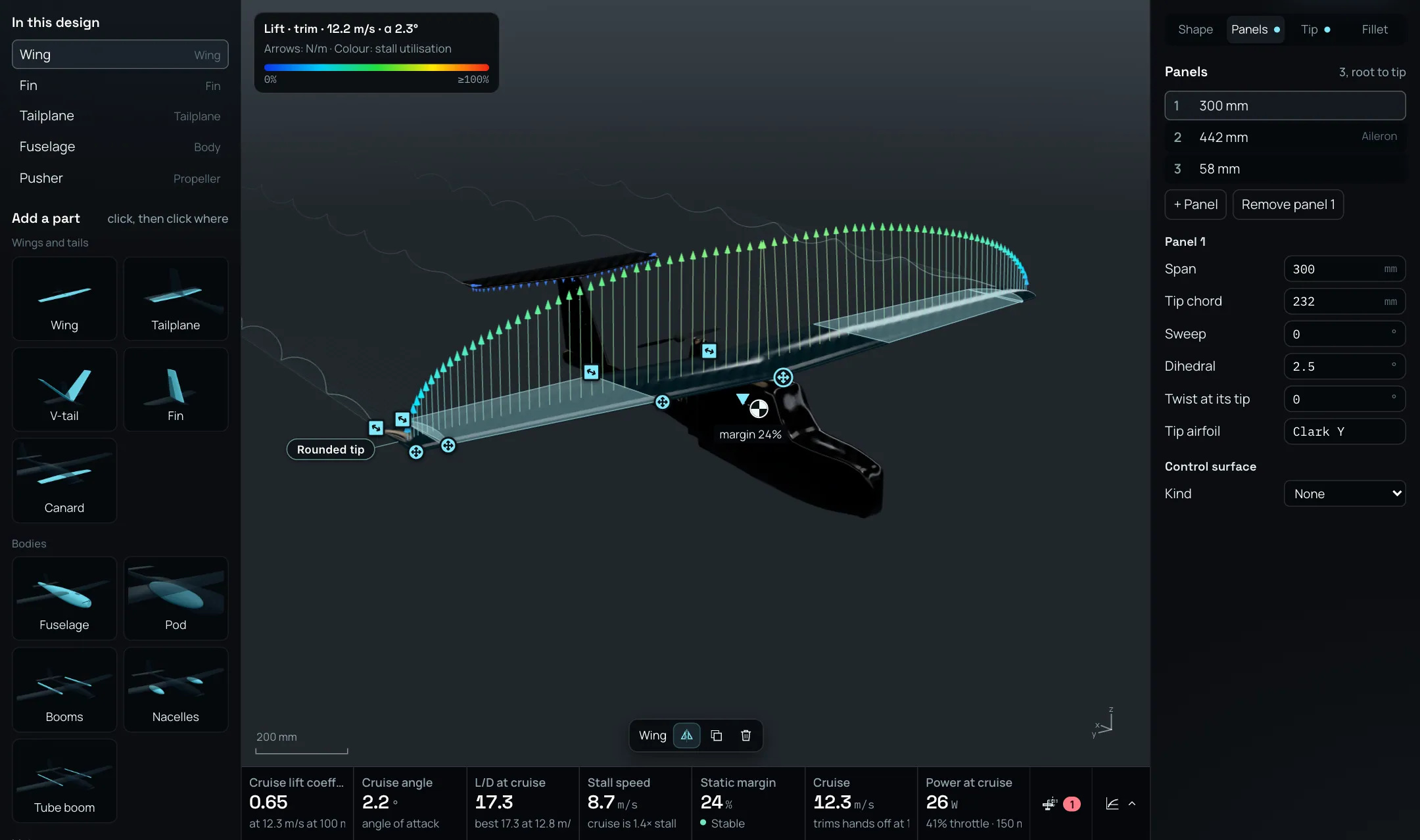
Pointing at a panel in the list shows it in the view.
You can also add a panel break in the view. Pick the wing and point at it: the view shows the section there and the text Click: a panel break here, with the panel number and the share along it. Click to split the panel there. A panel too near its end, or an elliptic one, is not split, and the view says why.
To add a control surface, choose its kind in Kind under Control surface: Aileron, Flap, Elevon, Elevator, Rudder or Ruddervator. The usual kind for the part is marked usual here. Then set Hinge line (as a share of the chord), From and To (where along the panel it runs) and Deflection.
Tip
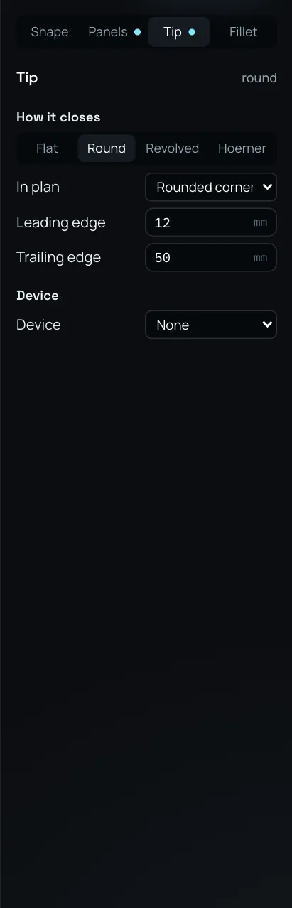
The Tip tab.
- How it closes
Flat, Round, Revolved or Hoerner.
- In plan
The shape of the tip seen from above: Square, Rounded corners, Elliptical or Raked, each with its own numbers.
- Device
None, Winglet, Split winglet, Raked tip or Endplates, each with its own numbers (for a winglet: length, cant, sweep, taper, toe and blend radius).
In the view, a chip near the tip names how it ends, for example Rounded tip. Select it to open a menu of the tip shapes.
Fillet
A fillet blends a wing or a tail into the part it meets.
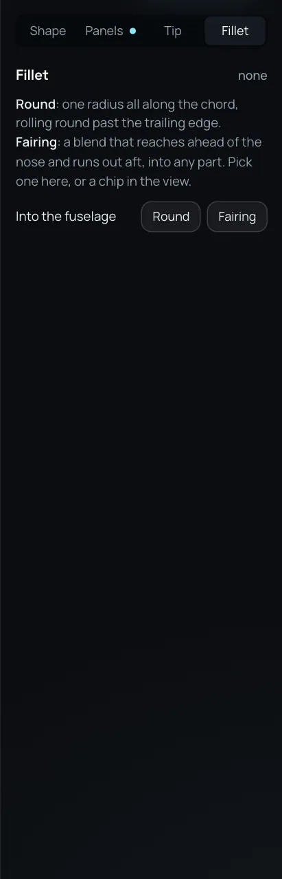
The Fillet tab of a wing that meets a fuselage.
Select the Fillet tab. If the part meets another part, the tab offers Round and Fairing. A chip Fillet into the fuselage in the view does the same. If the part does not meet another one, the tab says so: move its root or its tip into a body or a wing.
Select Round for one radius all along the chord, or Fairing for a fairing that is fitted to the two parts.
Change the numbers. For a round fillet they are Radius and Roundness. For a fairing the tab lists its sizes and Fillet checks.
Fit automatically finds values that build without a problem. Look at it brings the view in on the fillet. Remove takes it away.
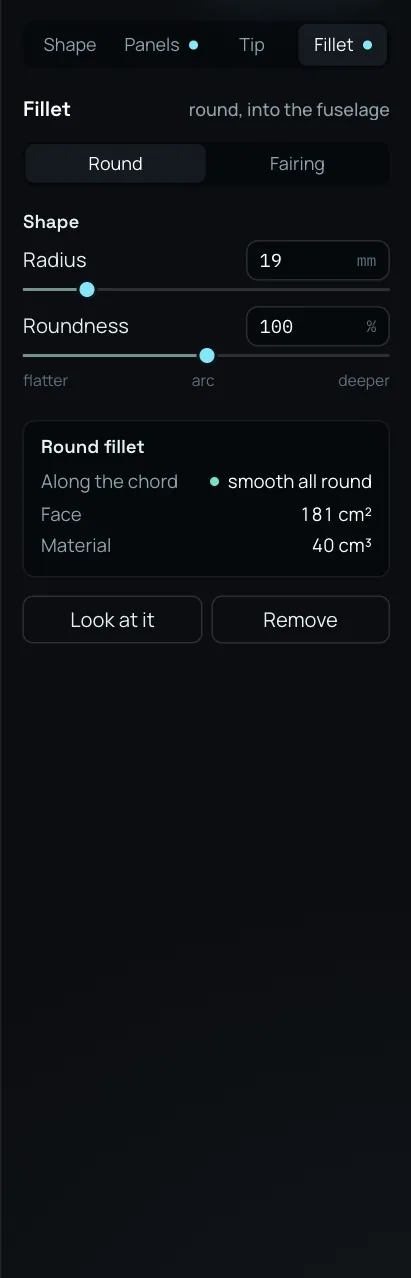
A round fillet.
Flight settings
The Flight group at the bottom of the right panel sets the aircraft as a whole.
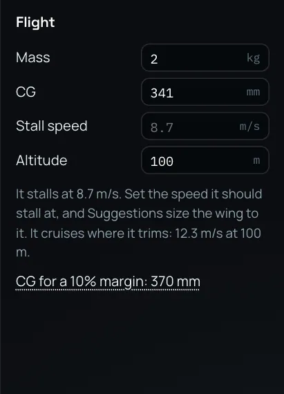
The Flight group.
- Mass
The take-off mass with everything on board, in kg.
- CG
The centre of gravity, behind the nose, in mm. The link CG for a 10% margin sets the CG where the static margin is 10% of the mean chord.
- Stall speed
The stall speed the aircraft should have, at sea level. It is empty until you set it, and then shows the speed worked out for the design in grey. When you set it, Suggestions size the wing to it. To clear it, delete the value.
- Altitude
The height of the cruise above sea level, in a standard atmosphere.
Under the fields, a line says where the aircraft stalls and where it cruises. The cruise is the speed at which it trims hands off.
Results
The strip under the view shows the answer of the aircraft as cards. It follows every edit.

The result cards.
Cruise lift coefficient |
CL at the cruise speed and altitude. |
Cruise angle |
The angle of attack at cruise. |
L/D at cruise |
The lift to drag ratio at cruise, with the best ratio and the speed for it. |
Stall speed |
The speed at which the wing stalls, and the ratio of the cruise speed to it. |
Static margin |
The distance between the neutral point and the CG as a share of the mean chord, with the word Stable or Unstable. |
Cruise |
The speed at which the aircraft trims hands off. |
Power at cruise |
The electric power at cruise, the throttle and the flight time. For an aircraft with no motor the card is Sink at cruise. |
After an edit, each card shows how it changed from before: an up or a down arrow and the size of the change. The colour says whether the change is better or worse.
Select the chart button at the right end of the strip to open three charts: the lift curve, the L/D by speed, and the power to fly level. The cruise and the stall are marked on them.
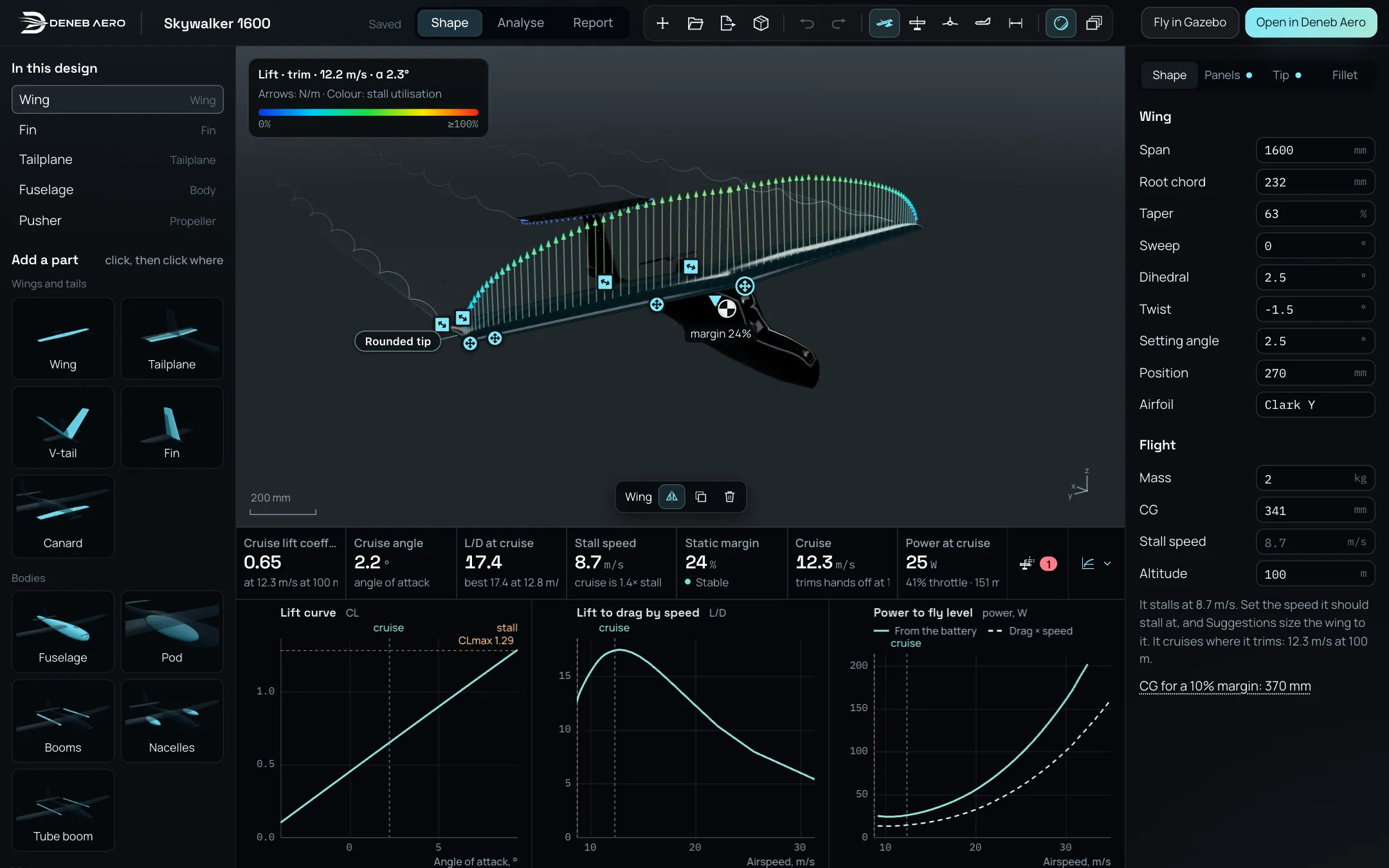
The charts open under the view.
While the airfoil polars are worked out, the bar shows Airfoil polars n of m. Until they are in, the section drag and the maximum lift are estimates from thickness and camber.
Suggestions
Select the suggestions button at the right end of the strip to open the Suggestions panel. The number on the button is the number of things to look at.
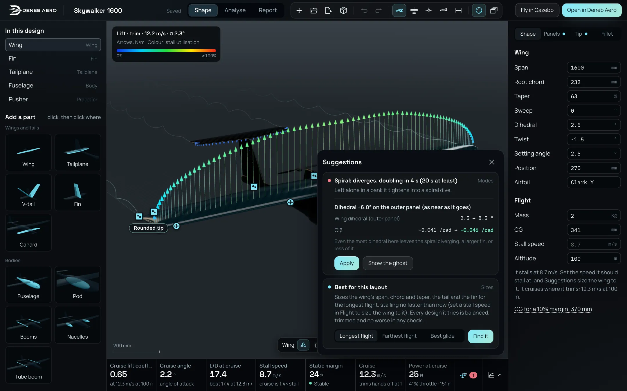
The Suggestions panel: a diverging spiral mode, and the best sizes for the layout.
Each entry says what is wrong, why, and what to change, with the numbers before and after.
Select Show the ghost to see the changed aircraft as a ghost over the aircraft.
Select Apply to make the change. It is one undo step.
Best for this layout searches for the span, the chord, the taper, the tail and the fin that give the longest flight (Longest flight) or the farthest flight (Farthest flight) at a stall speed no higher than now.
Views and the look
The tools in the bar change what you see. They are in the Shape mode only.

The bar. From the left: the name, the modes, new, open, export STEP, Gazebo package, undo, redo, the four views, frame, photoreal and layers.
- 3D view, Top view, Front view, Side view
Set the camera. In the 3D view, drag to turn the aircraft and use the wheel to zoom. The handles of a body’s outline are shown in the Side view and the Top view only.
- Frame the aircraft
Brings the whole aircraft into the view (F).
- Undo and Redo
Step back and forward through your edits (⌘Z and ⇧⌘Z, or Ctrl+Z and Ctrl+Shift+Z). A drag or a scrub is one step.
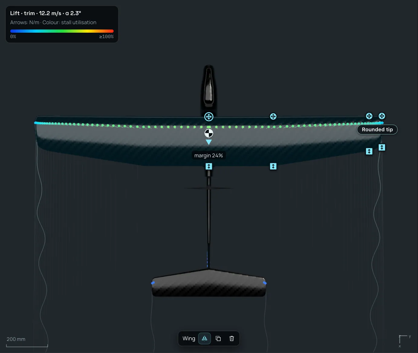
The Top view.
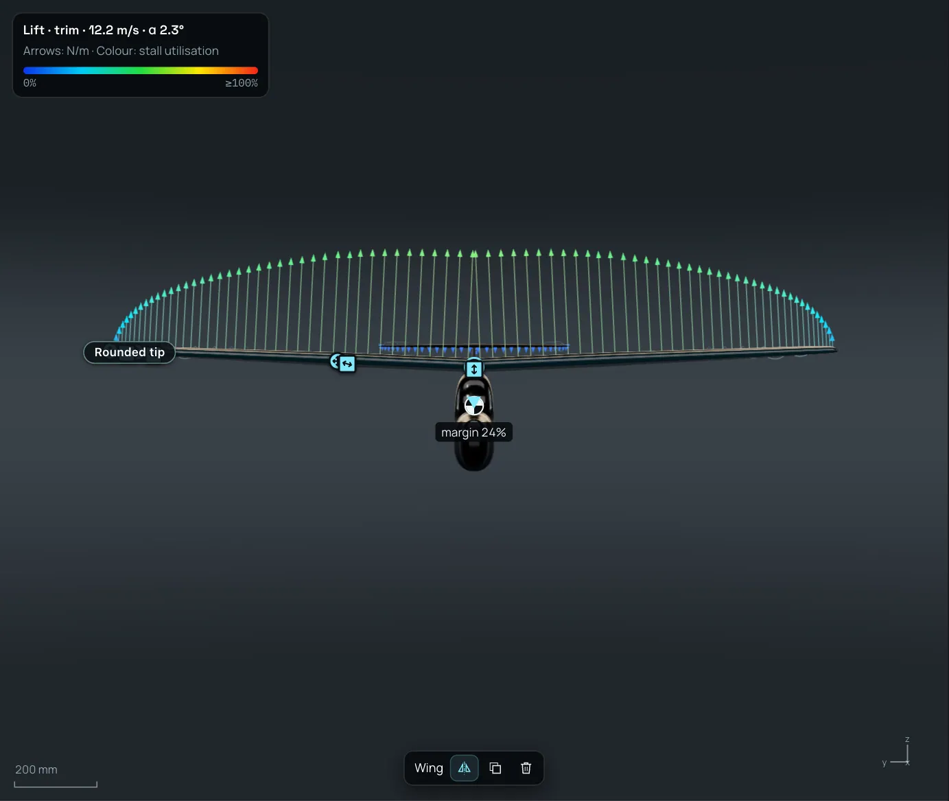
The Front view.
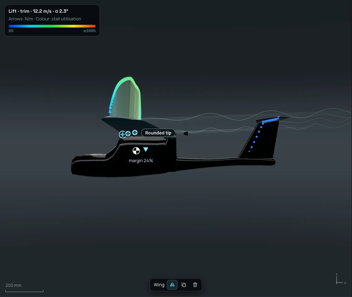
The Side view.
What the view shows
Select What the view shows to open a list of layers. Each is a checkbox.
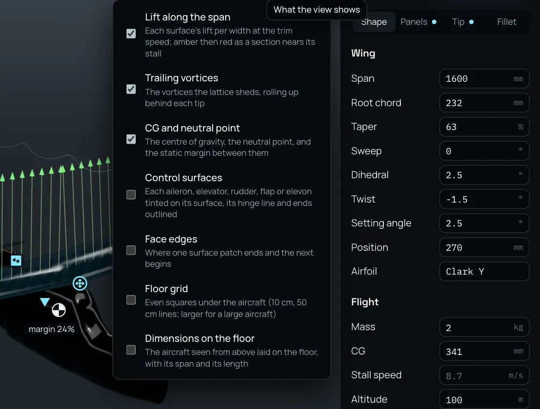
The layers.
Lift along the span |
The lift per width of each surface at the trim speed. The colour goes amber and then red as a section nears its stall. |
Trailing vortices |
The vortices the lattice sheds behind each tip. |
CG and neutral point |
The CG, the neutral point and the static margin between them. |
Control surfaces |
Each control tinted on its surface, with its hinge line and ends outlined. Off at first. |
Face edges |
Where one surface patch ends and the next begins. Off at first. |
Floor grid |
Even squares under the aircraft. Off at first. |
Dimensions on the floor |
The aircraft seen from above on the floor, with its span and length. Off at first. |
The imported model |
The imported file, for a design made by an import. |
Photoreal
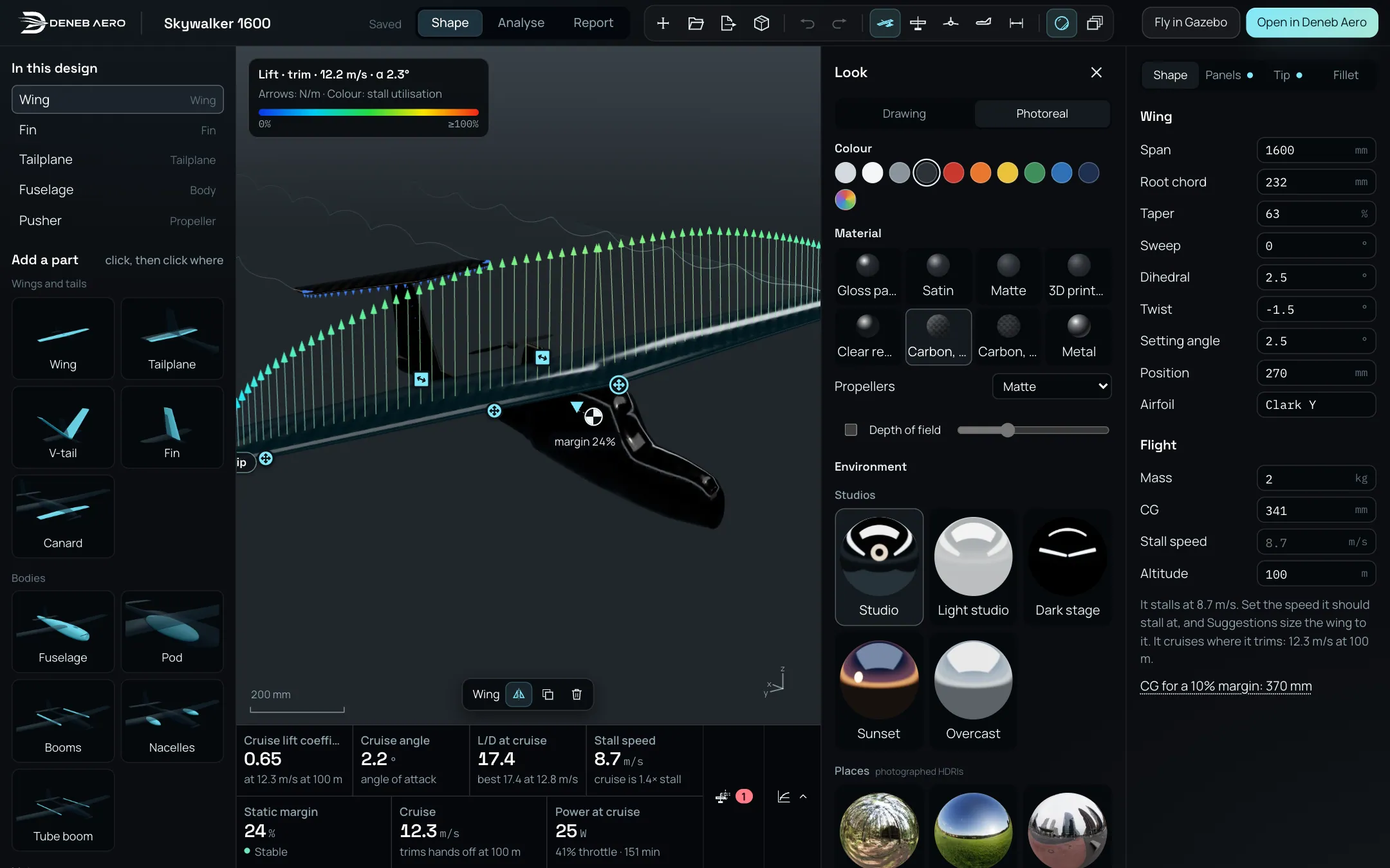
The Look panel at the right of the view.
Select Photoreal: colour, material, environment to open the Look panel. It sets how the aircraft is drawn. It does not change the aircraft or its numbers. The choices are kept in this browser.
- Drawing and Photoreal
The plain drawing, or the photoreal rendering.
- Colour
One of the swatches, or any colour with the last swatch.
- Material
For example Gloss paint, Satin, Matte, 3D printed and Metal. Propellers sets the material of the propellers.
- Depth of field
Blurs what is not at the focus. The slider sets the strength. You can pick the focus on the aircraft.
- Environment
A studio (Studio, Light studio, Dark stage, Sunset, Overcast), a photographed place, or your own picture. A place can be On its ground or A sphere round it. Your own picture is a 2:1 panorama (
.hdr,.exr,.jpg,.pngor.webp) of up to 400 MB. It stays in this browser.